| It has been mentioned several times that the input stage
of an active receiving antenna is easily damaged by lightning in the vicinity
due to the very high input impedance of the amplfier.
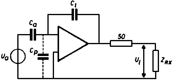
Several years ago Dr. (now professor) E.H. Nordholt of the Technical University Delft in The Netherlands developed an alternative design for an active antenna that does not suffer from this problem. Instead of making the input impedance very high it has been made very low by means of negative feedback. As a result the E-field probe, a piece of copper tube of 50cm long and 3cm diameter, now feeds a current into the FET at the input. Because of the probe's capacitive impedance the current increases with frequency at 6dB/octave. >This is compensated by negative feedback. Nordholt calls it an "integrating transimpedance amplifier in order to obtain a frequency independent transfer of the antenna signal." The principle is shown here.
The active antenna has a frequency response that is flat from 5kHz to over 30MHz. It stays linear in field strengths up to 10V/m. The output power is more than 100mW. Great attention has been given to proper noise behaviour ("noisemanship"). The input is protected by diodes against high voltages. Because signal voltages at the input are very small due to the low input impedance little signal current flows into the diodes and they do not impair the favourable characteristics of the active antenna. In a test the antenna was not damaged by sparks jumping to the probe from a car ignition coil.
The circuit diagram came from an article by Nordholt in a Dutch magazine. In the diagram you find "ferriet kralen". You probably guessed these are ferrite beads. At the gate of the input FET is a resistor of 1 giga-ohm. This high value is dictated by the lower frequency limit of 5kHz. If you would be happy with a lower limit of, say, 50kHz a resistor of 100 Megohm would be enough. Still a high value but it can be made by a string of lower value resistors in series. For more information see: E.H. Nordholt, D. van Willigen: "A new approach to active antenna design", IEEE Transactions on Ant. and Prop., vol. AP-28, no. 6, November 1980. 73,
|